Standing Seam
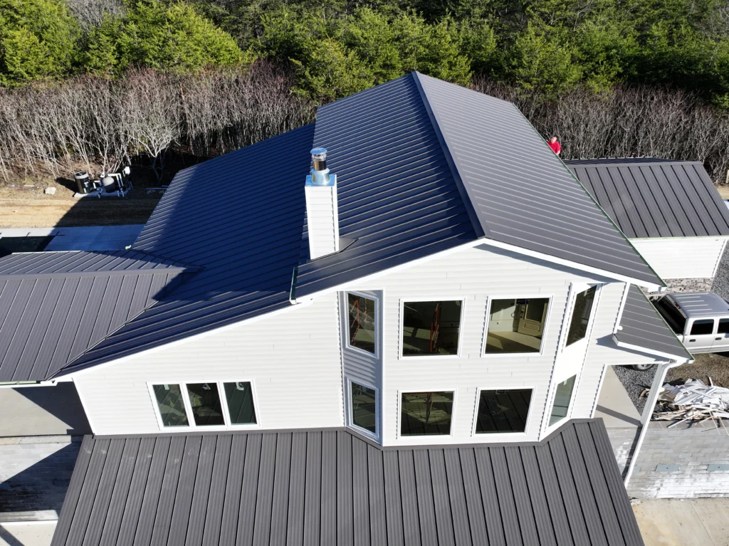
We have created a guide for the installation of standing seam panels. The guide includes step-by-step instructions and helpful tips to ensure a successful installation. If you have any questions regarding the guide or if you need any assistance with the installation process, please do not hesitate to reach out to us.
Panel Overview
Available Finishes: Akzo-Nobel Cerama-Star 1050 Select, Akzo Nobel Frost, Galvalume* (Other finishes available by request)
Warranty: Lifetime (Limited) Film Integrity, 30-Year Chalk, 30-Year Fade (With certain exceptions and limitations, explained in our Warranty detail)
Gauges: 26G Standard, 24G available by special order
Profile: 12” or 16” Net Coverage, with ¾” rib height. 12” Solid or Vented Soffit available. Striations on panel available by request. Panels are cut to ordered length.
*Galvalume is a trademark of BIEC International

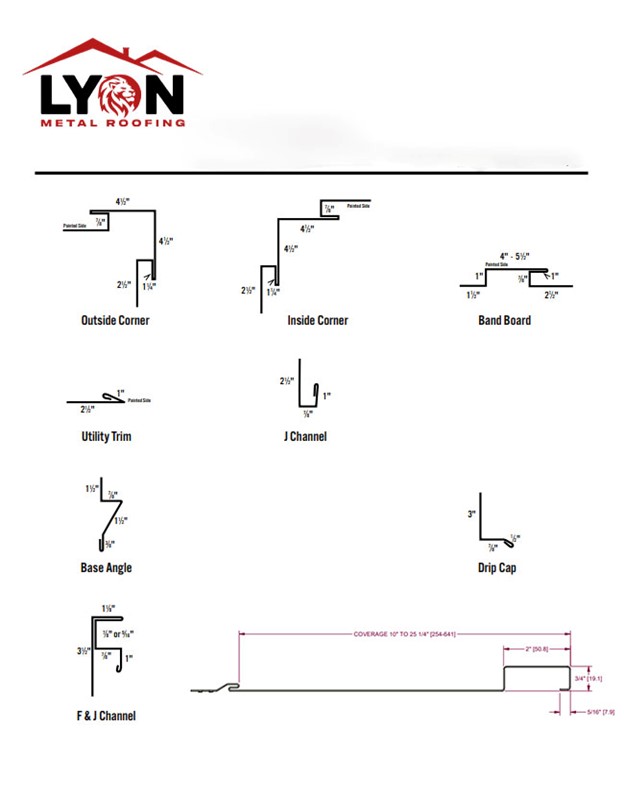
Trim Detail
Gable End Installation
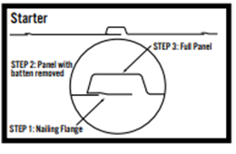
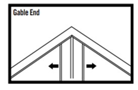
To ensure that the center of the panels lines up with the center of the gable, use the following installation steps:
- Start installing at the center and install outward to the right and
left sides of the building. - Cut the nailing flange portion from a full-length panel
(See Drawing) - Fasten this to the center of the gable, so that the center batten
will line up with the peak of the building. - Cut the batten off of a full-length piece. Then, fasten this piece and tuck the cut edge into the nailing flange, fastened in Step 2.
(See drawing) - Now, you will have two nailing flanges, with open hems, facing
each other. - Now, you can install the battens into both of these nailing
flanges, and continue installing the panels to the right and the left.
Base Angle / Rat Guard
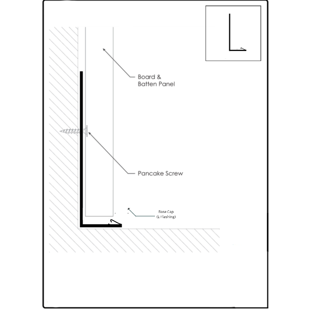
Base Angle/Rat Guard, is used at the bottom of the panels. It should be installed in a straight line along the skirtboard, using a pancake head screw. The panels should be installed so that the panel
can move at least ¼” off of the base angle/rat guard. Once your pancake head screw has been fixed into the skirtboard, cover with a high-grade exterior house tape.
Base Cap
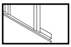
Used in areas with a flat surface (i.e., a solid deck, porch, concrete pad, etc.) where base/rat guard cannot be used. This trim will be secured with pancake head screws, and then the screw fixture
will be covered with a high-grade exterior house tape.
Hanging Panels
Board and Batten Siding should be installed over a solid deck of OSB, Plywood, or lathes (minimum of 18” on center). Board and Batten has the potential to oil can, or be wavy, on the flat part of the panels. This can occur due to the 10” or 14” flat area between the battens. Using striations can reduce the potential for oil canning to occur, but is not guaranteed to eliminate it. In relation, shortening the panels is another way to lower the risk of oil canning. (To do this, you can either split your gable panels, or reduce the wainscoting.)
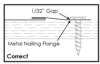
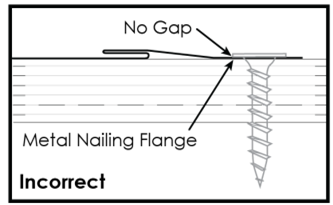
In order to allow the panels to “hover”, center fasteners within the nailing flanges. Fasteners should be drive in straight, as driving them in at an angle, can promote the formation of oil canning. Be sure there is an approximate 1/32” gap between the head of the fastener, and the metal nailing flange. (See illustration) Metal board and batten should be installed over the manufacturer’s recommended form of substrate.
When installing these board and batten panels, it is important to ensure there is room for vertical expansion between the panels. DO NOT over-tighten your fasteners! The panels should be fastened loosely, to allow them to “hover” against the substrate.
Doors, Windows, and Other Openings
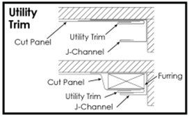
When panels are placed against the side of a window or door opening, utility trim should be installed inside of the J-Channel to protect the edge of the panel. This will also prevent the panel from chattering.
(See Illustration) If the panel terminates on the intermediate portion of the batten, you may need to use a furring strip to build up behind it. (See illustration)
Outside Corners
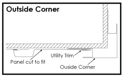
Because the nailing flanges are hidden behind the finished wall panels, outside corners should be installed before fastening any panels. They require the use of utility trim inside the built in J-channel, on both sides of the outside corner. Utility trim will ensure the cut edge of the panel is protected, and hidden from view. If the cut on the last panel happens to land on the intermediate portion of the batten, you may need to build up behind it, with a furring strip. (As illustrated in the utility trim diagram, in the previous section) Once this trim piece is fixed into place with pancake head screws, the screws will then be covered with a high -grade exterior house tape.
Panel Transitions
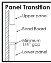
It may be necessary/desired to make a vertical break, or transition, within the wall panels. This can happen, when wainscoting is used, and at the gable ends of the building. These breaks in the wall panels provide both aesthetic appeals, and the ability to reduce probability of oil canning. When a break occurs, a band board trim is used between the top and bottom panels. Allow a minimum ¼” gap between the top of the bottom panel and the band board trim. This will allow space for vertical expansion to occur. This trim piece will be fixed into place with pancake head screws, then the screws will be covered with a high-grade exterior house tape.
Inside Corner Detail
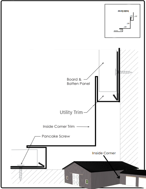
Inside corner trim is used where areas two inner-corner inside walls meet. Secure each trim piece on top of the boards using pancake head screws, while ensuring that the fasteners penetrate the wood framing. Seal the joint between the inside corner trim and the siding with high-grade exterior house tape.
Outside Corner Detail
Outside corner trim is used in areas where two outer corner walls meet. Secure each trim piece on top of the boards, use pancake head screws, while ensuring that the fasteners penetrate the wood framing. Seal the joint between the outside corner trim and the siding with high-grade exterior house tape.

Band Board Detail
Band board trim is used to join vertical sections of Board and Batten panel. Utility trim should be used on the lower side of your panel. Band board trim will then lock into the utility trim, and fasten directly into the wall substrate. The higher board and batten panel will then install directly over the high side of the band board trim.

Rat Guard / Base Guard Detail
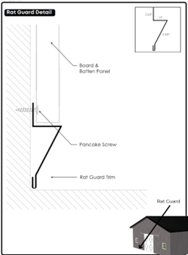
Rat Guard/Base Guard is used as base trim at the bottom of a well. This fastens directly to the wall substrate using a pancake head screw. Board and Batten wall panel is then installed over the Rat
Guard/Base Guard, resting on the ledge of the trim. This trim piece will be fixed with pancake head
screws, and the screws will be covered with a high-grade exterior house tape. Please remember to leave ¼” between the bottom of the panel and the Base Guard/Rat guard trim, to allow vertical expansion to occur.
Drip Cap Detail
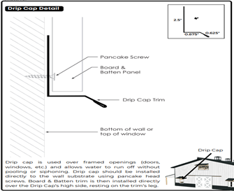
Drip cap is used at the top of windows and doors to divert water, and in some cases, at the bottom of the
wall. Allow a minimum ¼” gap from the bottom of the board and batten panel to the drip cap trim, to allow room for vertical expansion to occur. This trim will be fixed with pancake head screws, and then the screws will be covered with a high-grade exterior house tape.
**Drip Cap Trim can be used as a replacement/substitute for Base Guard/Rat Guard trim*
F & J Channel Detail
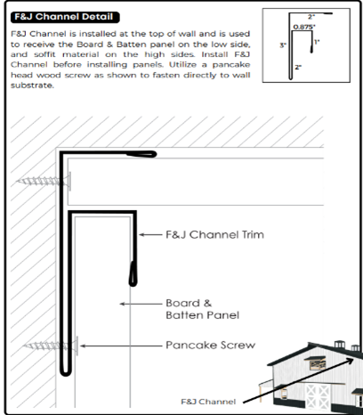
F & J Channel is installed at the top of the wall, and used to receive the board and batten panel on the low side, and soffit material on the high sides. Install F & J Channel before installing panels. Utilize
a pancake head wood screw, as shown, to fasten directly into the wall substrate. When pancake head screw is fixed into the wall substrate, then cover with a high-quality exterior house tape.
J Channel Detail
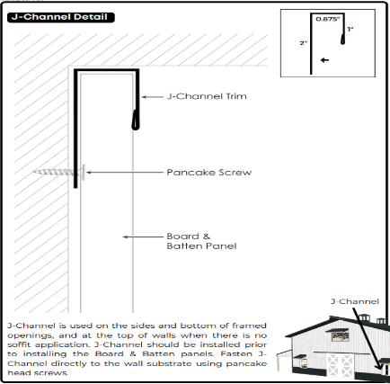
J-Channel is used on the sides and bottom of framed openings, as well as at the top of walls when there is no soffit application. J-Channel should be installed prior to installing the board and batten panels. Fasten J-Channel directly into the wall substrate, using pancake head screws. When pancake head screw is fixed into the wall substrate, then cover with a high-quality exterior house tape.
